


3 Phase Motor Forward Reverse wiring
Understand the 3 phase motor reverse forward starter power wiring with detailed diagram and instructions for safe and efficient motor direction control.

3 phase motor forward reverse control
The 3-phase motor reverse-forward starter power waving takes the two contactors to be used where one is the forward and the other being reverse. Through these starters, the direction of the motor changes by exchanging two phases and interlocks to avoid simultaneous operation thus allows safe control.
Formula & Table Summary:
Voltage (V): 400V line-to-line supply
Current (I): Motor rated current
Operation: Forward contactor connects phases normally; reverse swaps two phases
Safety: Electrical and mechanical interlocks prevent simultaneous starter activation
forward reverse starter connection
The 3-phase motor reverse-forward starter power wiring is built as a way to change the direction of a 3-phase motor, a starter containing forward contactors and reverse contactors. Such a wiring arrangement has the capability of safely allowing the motor to move forward and backward by switching two phases. A forward starter makes normal phase connections, whereas a reverse starter interchanges any two phases in order to reverse the motor direction. Interlocking occurs so that the starters cannot be enabled at the same time, and the motor and the circuit are not put at risk. This wiring is highly applicable in use with industrial motors of conveyors, hoer boosters, and motors that need to be controlled in direction. Decent wiring, safety protection, and precautions are necessary to prevent any type of damage and obtain effective work.
motor reversing starter wiring
| Starter | Phase Connections | Motor Direction |
|---|---|---|
| Forward Starter | L1 → U, L2 → V, L3 → W | Forward Rotation |
| Reverse Starter | L1 → U, L3 → V, L2 → W | Reverse Rotation |
Frequently Asked Questions - 3 Phase Motor Forward Reverse wiring:
What is the purpose of reverse and forward starters in motor wiring?
To control the motor rotation direction by swapping phase connections.
How do interlocks work in forward reverse starter wiring?
They prevent both starters from energizing simultaneously to avoid short circuits.
Can any two phases be swapped to reverse motor direction?
Yes, swapping any two of the three phases reverses motor rotation.
Is overload protection necessary in starter wiring?
Yes, to protect the motor from damage due to overcurrent.
What safety precautions should be taken during wiring?
Turn off power, use insulated tools, and follow wiring diagrams carefully.
Can this wiring be automated?
Yes, through motor starters with coil control circuits and interlocks.
What happens if both starters are energized together?
It causes a short circuit and can damage the motor and control system.
What types of motors use forward reverse starter wiring?
Mostly squirrel cage induction motors in industrial applications.
Is it necessary to label wires in motor starter wiring?
Yes, proper labeling prevents wiring mistakes and aids maintenance.
Can manual switches replace starters for direction control?
Manual switches are less safe and not recommended for high power motors.
Related Posts
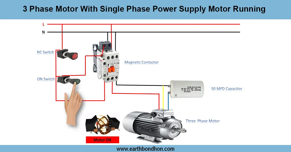
3 Phase Motor in Single Phase Connection
Learn how to run a 3-phase motor on a single-phase power supply using capacitor start or phase converter methods for reliable motor operation.
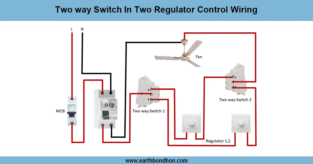
Two way switch fan regulator connection
Wiring diagram for controlling two separate light regulators from two locations using two-way switches for flexible ON/OFF control.
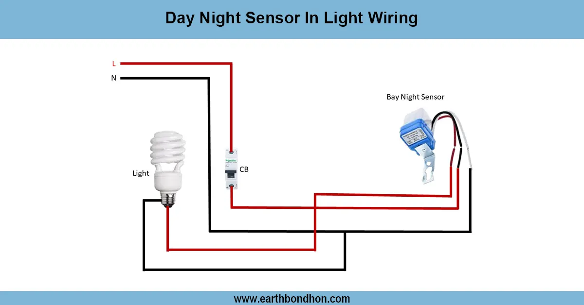
Day Night Sensor In Light Wiring
Wire a dusk-to-dawn (day-night) sensor to automatically control lights at sunset and sunrise. Includes wiring steps, safety tips, and common sensor types.
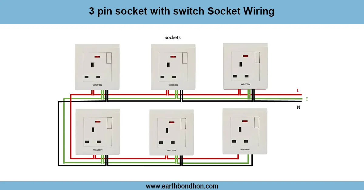
Power Socket Wiring Diagram
Learn how to wire a power socket with safety in mind. This guide includes diagrams, step-by-step instructions, and common wiring FAQs for home and industrial use.
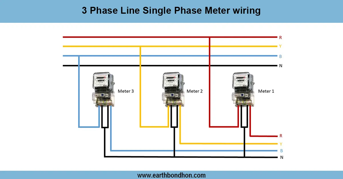
Three-phase to Single Phase Energy Meter
Learn how to wire a single-phase energy meter in a 3-phase line system safely and correctly with a clear wiring diagram and step-by-step instructions.

Bed switch connection wiring
Understand bed switch wiring with step-by-step diagrams, easy connection instructions, and common FAQs for safe bedroom lighting control.