

Three-phase to Single Phase Energy Meter
Learn how to wire a single-phase energy meter in a 3-phase line system safely and correctly with a clear wiring diagram and step-by-step instructions.

single phase energy meter wiring
In 3 phase line single phase meter wiring, the single-phase meter measures one side of a 3 phases supply (L1) and the neutral. The input terminals of the meter are connected to the incoming phase and neutral wire and the output to the load. This will see to it that meter gives the correct consumption of power at the single phase load connected to a 3-phase supply. Proper wiring helps avoid tapping of the meter causing damage, and also helps one read the energy properly making it easy to monitor it.
3 Phase Line Single Phase Meter Wiring Summary & Formula:
Voltage (V): 230V single phase from one phase line of 3-phase supply
Current (I): Load current passing through meter coil
Power (P):P = V × I × Power Factor
Wiring Connections: Phase line (L1) → Meter input (Line) → Meter output (Load line)
Neutral (N) → Meter input neutral → Meter output neutral → Load neutral
3-phase to single-phase meter wiring
The single phase meter 3 phase line connections are where a single phase energy meter is connected under one three-phase supply phase and the neutral line. The arrangement is most often found in situations where single-phase load measurement, but not a three-phase supply system, is desired. The meter indicates voltage and current in one phase line (L1) and in the neutral (N). The correct connection is by taking the phase line input and output terminal of the meter in series with the load and neutral lines are either connected accordingly. This must be wired such that current passes through the meter coil to measure accurately, and any such connections must comply with electrical safety regulations. This is cost-effective in terms of demonstrating a single-phase load on a supply that has 3 phases.
single-phase meter connection diagram
| Terminal | Connection | Description |
|---|---|---|
| Line Input (1) | Phase line from 3-phase supply (L1) | The incoming phase supply to the meter |
| Line Output (2) | To load the phase line | Outgoing phase supply after the meter |
| Neutral Input (3) | Neutral line from supply | Neutral incoming connection |
| Neutral Output (4) | To load neutral | Neutral outgoing connection |
Frequently Asked Questions - Three-phase to Single Phase Energy Meter:
Can a single-phase meter be used on a 3-phase line?
Yes, by connecting it to one phase and neutral lines for measuring single-phase load.
Which phase line is used for single-phase meter wiring in 3-phase?
Typically, phase line L1 is used but any one phase can be selected.
Is neutral connection necessary for single-phase meter wiring?
Yes, neutral is required to complete the circuit and provide accurate measurement.
Can this wiring measure three-phase loads?
No, it only measures the load connected to the single-phase meter line.
What voltage does the single-phase meter read in this setup?
It reads the voltage between the selected phase line and neutral, usually 230V.
What precautions should be taken during wiring?
Ensure correct terminal connections and turn off power during installation for safety.
Can multiple single-phase meters be connected on a 3-phase supply?
Yes, one meter per phase can monitor loads separately.
Does this wiring require a special transformer?
No special transformer is required for single-phase meter on 3-phase line.
What happens if the meter is wired incorrectly?
Incorrect wiring can cause meter damage or inaccurate readings.
Is this wiring method economical?
Yes, it’s cost-effective for monitoring single-phase loads on 3-phase supply systems.
Related Posts
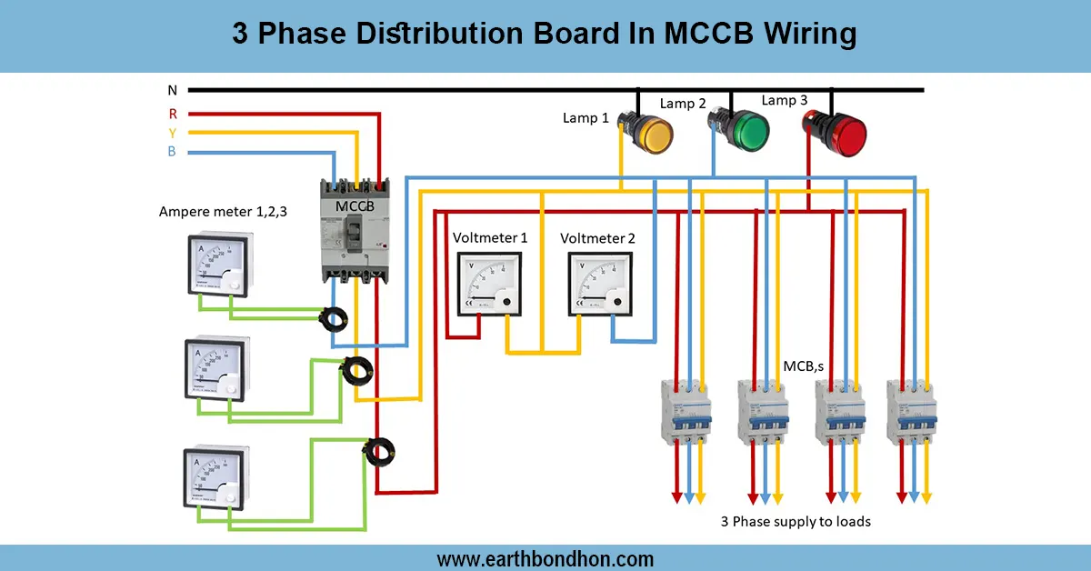
3-phase distribution Board wiring circuit
Complete wiring diagram for 3 phase distribution board with MCCB, showing connections for incoming supply, breakers, and load distribution for safe power control.
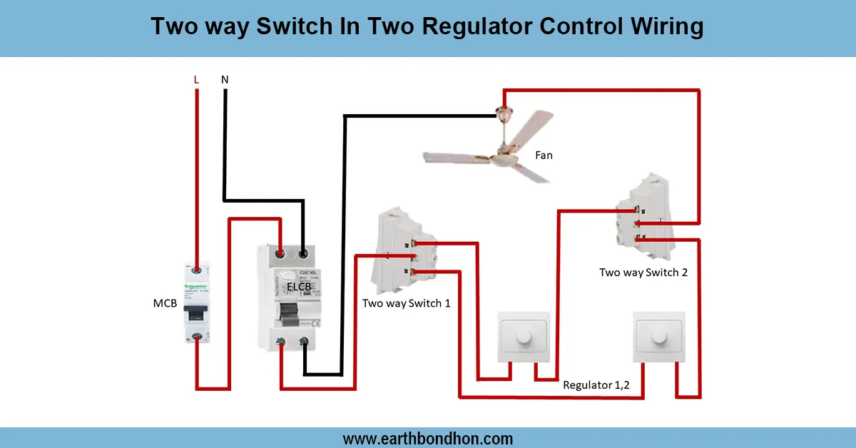
Two way switch fan regulator connection
Wiring diagram for controlling two separate light regulators from two locations using two-way switches for flexible ON/OFF control.

2 Way Light Switch wiring 4 Methode
A 2-way light switch wiring diagram helps control a single light from two different locations. Common in staircases, long hallways, or large rooms.
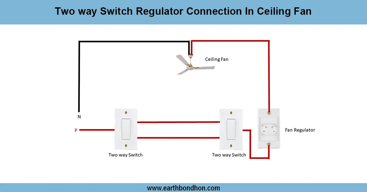
Ceiling Fan Regulator connection
Wiring diagram showing how to connect a two way switch with a regulator to control ceiling fan speed and ON/OFF from two locations.
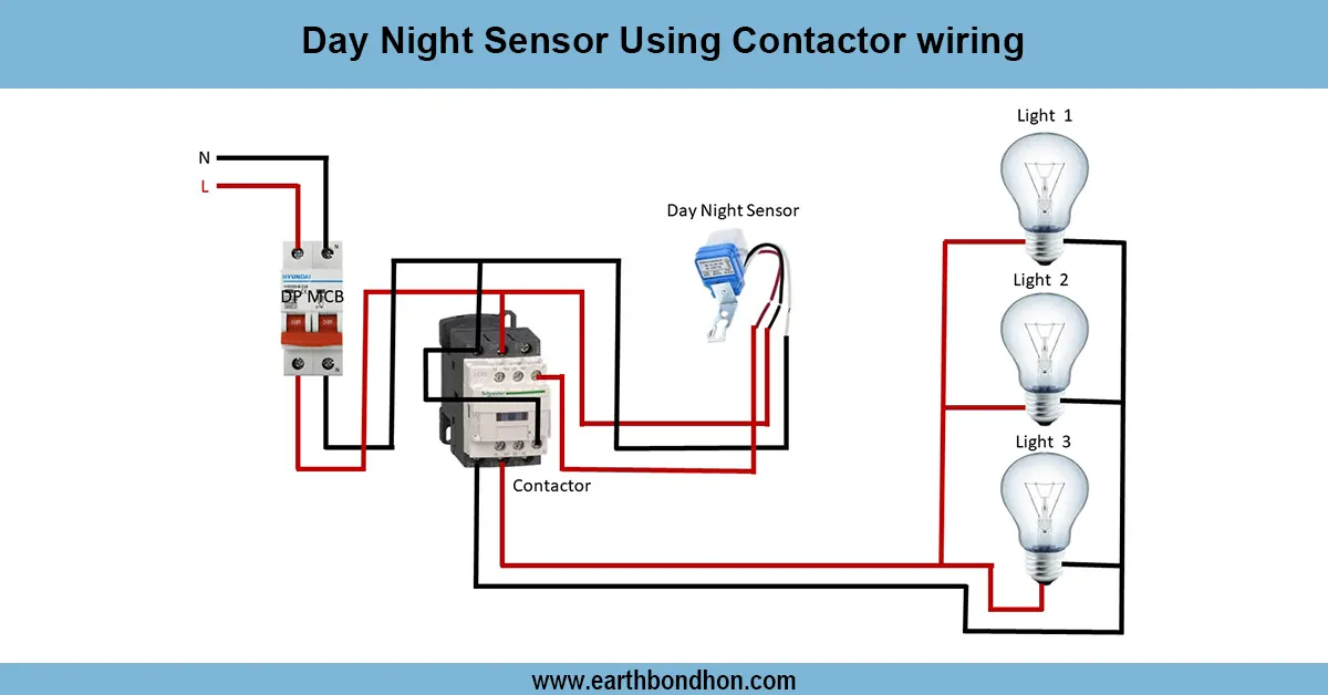
Day Night Sensor Using Contactor wiring
Automatic lighting control using a day-night sensor with a contactor for high-load circuits, ensuring safe, efficient, and hands-free operation.
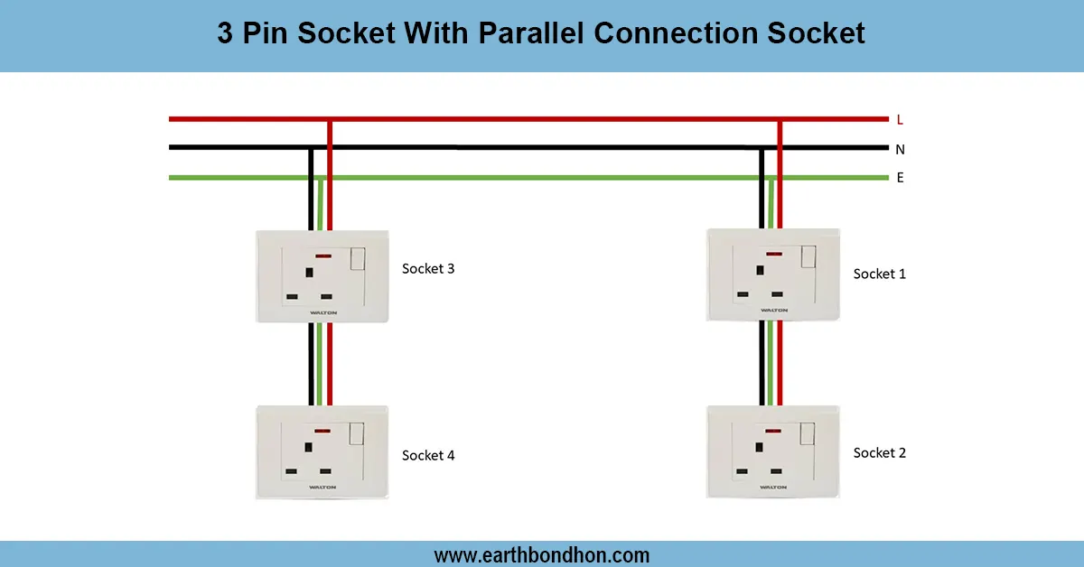
3 pin socket connection diagram
Learn how to connect a 3-pin socket properly using live, neutral, and earth wires. Ideal for household or office electrical installations.