


3 Phase Motor Star Connection Diagram
Understand the 3-phase motor star connection wiring for motor starting and operation, including wiring steps and benefits of star configuration.

star connection wiring diagram
In a 3-phase motor star connection, all 3 windings go to a neutral point and free ends go to the supply phases. This minimizes starting current by putting less voltage on each winding so that the start is soft. Large motors require Star connection in order to start.
3 Phase Motor Star Connection Formula & Summary:
Line Voltage (VL): Voltage between any two supply phases
Phase Voltage (Vph):Vph = VL / √3
Starting Current: Reduced to 1/√3 of delta connection
Connection: Windings connected at one point (neutral), forming star (Y)
motor starting star connection
The 3-phase motor star connection is a usual wiring practice where the three windings on the motor have a common shared neutral point, and this pattern takes the shape of a Y. This arrangement, applied mostly through the starting of the motor, limits the starting current and helps in getting smooth operation. In a star connection, each winding receives line voltage at a lower voltage (line voltage/ sqrt 3 ), and this limits the starting surge current. The motor can be switched to a delta connection and is able to run normally at full voltage then. Star connection is desirable as it helps to minimize mechanical strain and electrical demand when starting a motor. The wiring should have the connection of the end of the three windings terminated between each other to make the neutral and the three phases provided to the ends of the other three windings. The configuration is fairly common with industrial motors to enhance efficiency and a longer lifespan.
star wiring motor diagram
| Terminal | Connection | Description |
|---|---|---|
| U1, V1, W1 | Connected to supply phases L1, L2, L3 | Motor phase inputs |
| U2, V2, W2 | Connected together to form a neutral point | Common star point |
Frequently Asked Questions - 3 Phase Motor Star Connection Diagram:
What is star connection in a 3 phase motor?
It connects all three windings at a common neutral point, forming a Y shape.
Why use star connection for motor starting?
To reduce starting current and mechanical stress on the motor.
How is phase voltage related to line voltage in star?
Phase voltage equals line voltage divided by square root of 3.
Can star connection be used for normal running?
Typically, motors switch to delta for normal running after starting.
What terminals form the neutral in star connection?
The ends U2, V2, and W2 of motor windings are connected together.
Does star connection reduce power output?
No, it reduces starting current but power output remains the same at running.
Is star connection safe for all motors?
It is commonly used for large motors requiring reduced start current.
How to identify star connected motor terminals?
Look for U2, V2, W2 connected together inside the motor terminal box.
What happens if star connection is wired incorrectly?
Motor may fail to start or run inefficiently, risking damage.
Is star connection suitable for single phase motors?
No, it is specific to three-phase motors only.
Related Posts
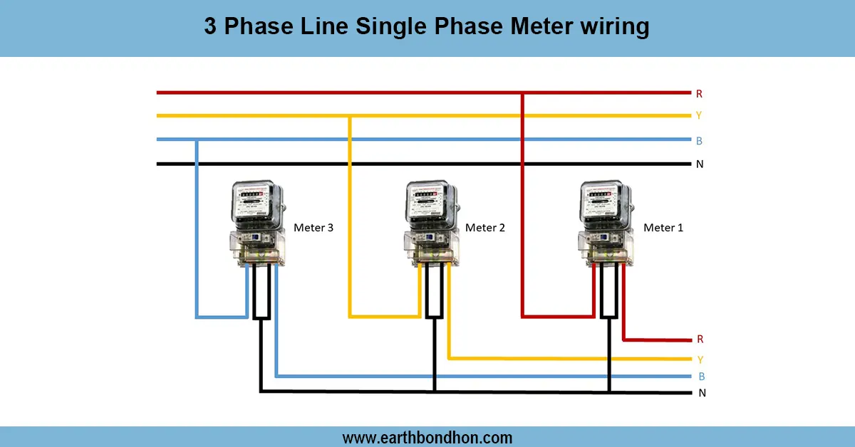
Three-phase to Single Phase Energy Meter
Learn how to wire a single-phase energy meter in a 3-phase line system safely and correctly with a clear wiring diagram and step-by-step instructions.

Corridor Hallway Wiring
Learn how to wire corridor hallway lights using one-way or two-way switch systems. Ideal for staircases, passages, and commercial buildings.
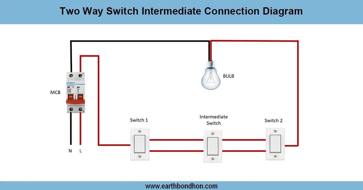
2 Way light switch wiring
Wiring diagram for controlling a light from three or more locations using two way and intermediate switches for flexible ON/OFF control.

Switch and Socket Connection Diagram
Understand switch and socket connection diagrams for safe and efficient home wiring. Step-by-step wiring guide for switches and electrical sockets.
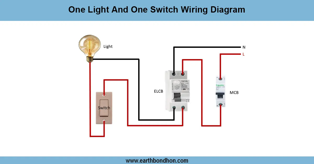
One Light one Switch Connection
Learn how to wire a single light with a single switch. Ideal for basic electrical setups in rooms, bathrooms, and small utility areas.
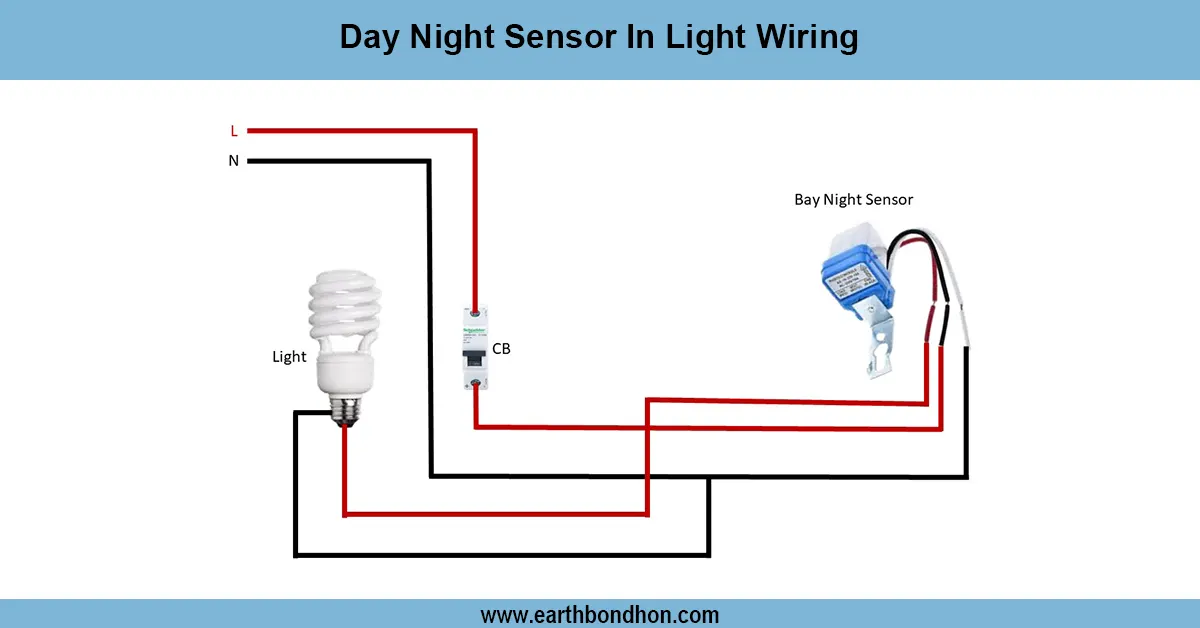
Day Night Sensor In Light Wiring
Wire a dusk-to-dawn (day-night) sensor to automatically control lights at sunset and sunrise. Includes wiring steps, safety tips, and common sensor types.