


8 Pin timer Relay wiring
Learn the pin configuration and wiring method for an 8‑pin timer relay to control loads with delay. Includes coil connections, NO/NC contacts, and timing logic.

8 pin timer relay wiring
Learn the pin configuration and wiring method for an 8‑pin timer relay to control loads with a delay. Includes coil connections, NO/NC contacts, and timing logic.
Wiring Formula Summary:
Relay Coil Voltage: V = IR (Use Ohm’s Law to check relay current requirement)
Delay Function: Depends on timer module — ON Delay or OFF Delay logic.
- Pin 2 & 7: Coil connections
- Pin 1: COM 1 → Pin 3 NO, Pin 4 NC
- Pin 8: COM 2 → Pin 6 NO, Pin 5 NC
timer relay wiring diagram
An 8‑pin timer relay is used to control electrical loads with a preset delay using a DPDT contact arrangement. It provides both normally open and normally closed outputs across two separate channels. Understanding its pin configuration helps ensure safe and efficient circuit wiring for motors, lamps, and automation systems.
8 pin timer connection
| Pin | Function | Type | Notes |
|---|---|---|---|
| 2, 7 | Coil | Power Input | Apply voltage to activate timer |
| 1 | COM 1 | Contact | Switches between NC (4) & NO (3) |
| 8 | COM 2 | Contact | Switches between NC (5) & NO (6) |
Frequently Asked Questions - 8 Pin timer Relay wiring:
What is an 8‑pin timer relay?
A timer relay with coil, two common contacts each with NC and NO terminals.
Which pins are for the coil?
Pins 2 and 7 are used for the coil (L and N supply) on most models.
How are relay contacts arranged?
Pins 1 & 8 are COM; 1 NC‑4/NO‑3; 8 NC‑5/NO‑6 contacts.
Which pins are NO and NC?
Pin 3 & 6 are NO; pin 4 & 5 are NC relays.
Can the timer drive motors?
Yes, in auto ON/OFF circuits for motors using appropriate rating.
Is this a DPDT timer?
Yes, two separate poles each with NC/NO outputs.
What voltage is coil rated?
Common options: 12 VDC, 24 VDC, 110 VAC, or 220 VAC depending on model.
Can I wire it without a diagram?
It’s risky; pin numbering and logic vary—always follow manufacturer pinout.
Do I need MCB protection?
Yes—use a SP or DP MCB/RCCB rated for coil and load currents.
How do I use it for delay ON/OFF?
Apply coil voltage to start delay, contacts change after set duration.
Related Posts
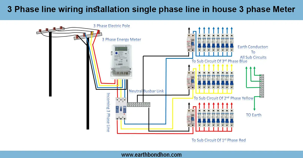
3 Phase Line to Single Phase Wiring
Learn 3-phase line wiring installation for a single-phase supply in a house using a 3-phase meter with step-by-step wiring, safety tips, and an accurate setup guide.
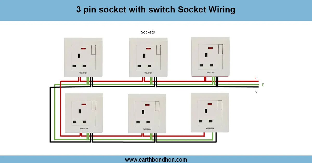
Power Socket Wiring Diagram
Learn how to wire a power socket with safety in mind. This guide includes diagrams, step-by-step instructions, and common wiring FAQs for home and industrial use.

Hospital wiring Diagram
Understand hospital wiring diagrams, including emergency systems, isolation panels, and backup supplies for safe and reliable healthcare facility operations.
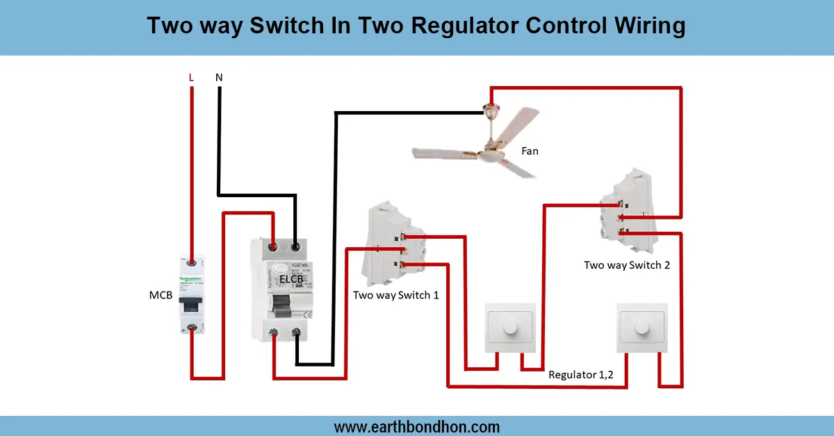
Two way switch fan regulator connection
Wiring diagram for controlling two separate light regulators from two locations using two-way switches for flexible ON/OFF control.
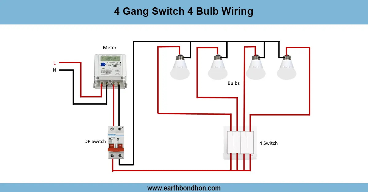
4 Gang Switch 4 Bulb Wiring
Learn how to wire a 4-gang switch to control 4 individual bulbs. Ideal for multi-light room setups with simple step-by-step wiring guide and diagram.

2 Way Light Switch wiring 4 Methode
A 2-way light switch wiring diagram helps control a single light from two different locations. Common in staircases, long hallways, or large rooms.