

Ceiling Fan Wiring Diagram
Learn how to wire a ceiling fan with a switch and regulator. Easy-to-follow diagram, explanation, and common FAQs for safe and efficient ceiling fan installation.

single phase ceiling fan wiring
Interested in a safe way of wiring a ceiling fan? Ceiling fan wiring diagram The diagram shows how a fan motor, switch, regulator, and power source connect together. This wiring step-by-step guide helps simplify the wiring so that you can be familiar with the live, the neutral, and the ground and how the capacitor and speed control of the fan collaborate. Whether being new to wiring and completing the project as a beginner or an electrician, this wiring guide will facilitate his intentions, as well as ensure safety in the application.
Formula & Table Summary:
- Live Line (L) → Switch → Regulator → Capacitor → Fan
- Neutral (N) → Direct to Fan
- Earth (E) → Fan body (optional for safety)
Regulator adjusts resistance, controlling voltage drop and speed.
fan switch connection diagram
A ceiling fan wiring diagram enables you to know the electrical connections required in order to have a safely operating fan. A fan normally consists of a working conductor, a neutral, and the earth conductor. In the case of speed control, the regulator is connected in series with the live wire. The capacitor in the fan is a necessity with regard to the successful starting and startuptorque. Of course, connections may differ, depending on how you are wired up, e.g., a regulator in one switch or a speed controller and switch. Knowing these diagrams is important in the context of electricians, homeowners, and those into the work of DIY. An analysis of the layout would help you to understand the correct way to connect every part, so as to reduce the chances of short circuits or heating. Conventional wiring codes should always be adhered to, and power should be switched off during installation.
ceiling fan wiring diagram
| Component | Wire Color | Connection Point | Function |
|---|---|---|---|
| Live (L) | Red | From Power to Switch | Power Input |
| Switch to Regulator | Red | Output of Switch | Speed Control Start |
| Regulator Output | Yellow | To Capacitor/Fan Terminal | Voltage Control |
| Neutral (N) | Black | From Power to Fan | Return Path |
| Capacitor | White | Between Fan Windings | Starting & Running Torque |
| Earth (E) | Green | Fan Body (if present) | Safety Ground |
Frequently Asked Questions - Ceiling Fan Wiring Diagram:
How do I wire a ceiling fan with a regulator?
Connect live wire through a switch to regulator, then to the fan. Neutral wire goes directly to the fan.
What color wires go where on a ceiling fan?
Typically red or brown for live, black for neutral, green for earth, and white for capacitor.
Can I install a fan without a capacitor?
No, ceiling fans require a capacitor to start and run properly.
Is earth wire necessary for a ceiling fan?
Earth wire is optional but recommended for metal body fans for safety.
Can I use a dimmer instead of a fan regulator?
No, dimmers are not suitable for fan speed control and may damage the motor.
How many wires are in a ceiling fan?
Usually 3 to 4 wires: live, neutral, earth, and a capacitor wire.
What happens if capacitor is connected wrongly?
Wrong connection can prevent the fan from starting or reduce its speed.
Can I connect a ceiling fan directly to a plug?
It’s unsafe. Use a proper switch and regulator circuit.
How do I test ceiling fan wiring?
Use a multimeter to check voltage at each terminal and continuity of windings.
Why does my fan hum but not spin?
Likely a faulty capacitor or wrong wiring. Check and replace as needed.
Related Posts
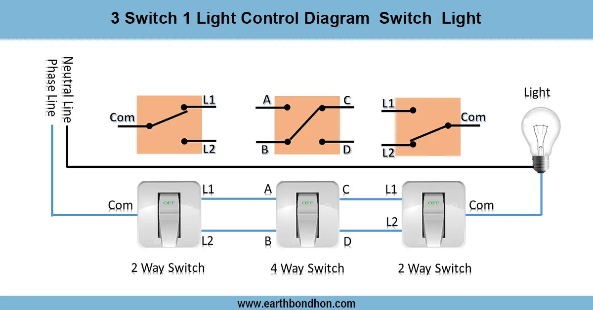
3 Switch 1 Light Wiring Diagram
Learn how to control one light using three switches with step-by-step wiring diagrams, circuit explanation, and real-life application tips for efficient electrical setups.
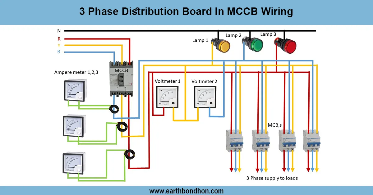
3-phase distribution Board wiring circuit
Complete wiring diagram for 3 phase distribution board with MCCB, showing connections for incoming supply, breakers, and load distribution for safe power control.
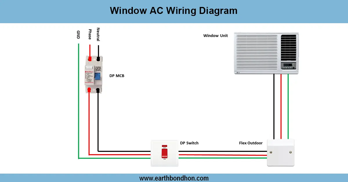
Window AC wiring
Detailed wiring diagram for window AC units covering power connections, thermostat wiring, compressor, fan motor, and safety components for safe operation.

Switch and Socket Connection Diagram
Understand switch and socket connection diagrams for safe and efficient home wiring. Step-by-step wiring guide for switches and electrical sockets.
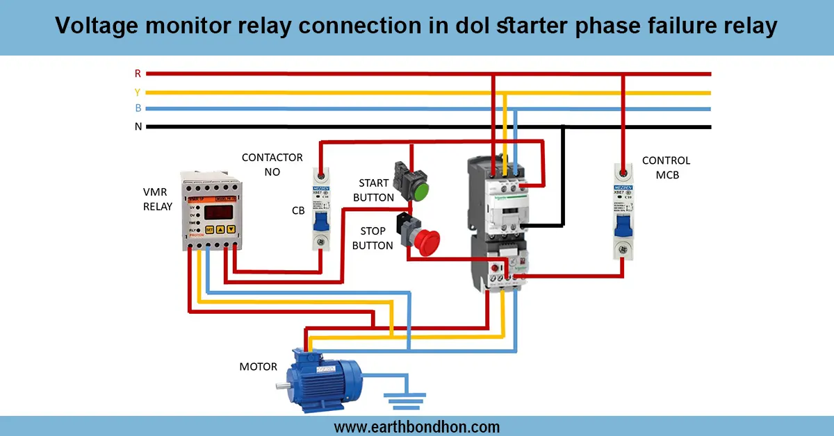
Voltage monitor Relay connection
Learn how to wire a voltage monitor relay in a DOL starter to protect 3-phase motors from phase loss, phase reversal, and voltage faults with easy connection steps.
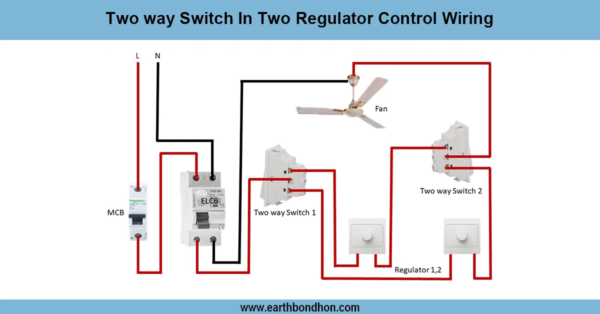
Two way switch fan regulator connection
Wiring diagram for controlling two separate light regulators from two locations using two-way switches for flexible ON/OFF control.
Earth Bondhon
Md. Jony Islam is a highly skilled professional with expertise in electronics, electrical, mechanical, and civil engineering, as well as finance. Specializing intransformer service and maintenance for 33/11kV substations, he ensures reliable and efficient electrical systems. His mechanical engineering skills drive innovative designs, while his financial acumen supports effective project budgeting. With a strong foundation in civil engineering, he contributes to robust infrastructure development. Md. Jony Islam's multidisciplinary approach ensures efficiency, quality, and reliability across all projects.