


Godown wiring circuit diagram
Learn how Godown wiring works to light one room at a time using multiple switches. Ideal for warehouses, corridors, and storage areas with energy-saving control.

godown switch connection
An example of what a wiring circuit diagram of a godown looks like is that of how we can use several lights having an individual switch with only one light ON during a circuit. This is a sequential lighting system that improves energy and is mostly applicable in long corridors, warehouses, or storage places. The circuit, which is designed in the godown with switches, ensures that no more than a single bulb is turned ON at a time, as each switch turns the previous one OFF and the current one ON. This tutorial gives the concept of working, arrangement, formula, and application of godown wiring.
Formula & Table Summary:
Formula: Only one switch (Sn) connects phase to the corresponding lamp (Ln) → Light ON = SWn = ON; All Other SW = OFF
one switch one light control
Godown wiring is one of the common means, which is applied in godowns, long corridors, and production halls where one point of light is necessary at a time. The idea itself is rather straightforward but still helpful: a couple of lights are linked by separate switches, and yet, only one of them works at any one time. This arrangement is energy efficient and prevents the use of lights in the unutilized areas. Each of the switches would be located next to the respective room or area so the staff could switch on a light only when entering that particular area. After pressing one of the other switches, the lamp that has been turned on goes off, and the one that has been selected becomes lit. This not only makes godown wiring economical but also safer since the overall load will be minimized. It is commonly applied in basements, schools, hospitals, and warehouses.
godown wiring diagram
| Switch No. | Switch Position | Light Status | Energy Usage |
|---|---|---|---|
| SW1 | ON | L1 ON | Active |
| SW2 | ON | L2 ON | Active |
| SW3 | OFF | OFF | Inactive |
| SW4 | OFF | OFF | Inactive |
Frequently Asked Questions - Godown wiring circuit diagram:
What is godown wiring?
It is a wiring method where only one light remains ON at a time, ideal for corridors and warehouses.
Where is godown wiring used?
Used in storage rooms, basements, godowns, long hallways, and industrial areas.
How does godown wiring save energy?
Only one light is powered at a time, reducing overall electricity usage.
Can godown wiring be automated?
Yes, using relays or smart switches for automated light control.
What switch type is used in godown wiring?
Standard one-way (SPST) switches are commonly used.
Is neutral shared in godown wiring?
Yes, all lights share the same neutral line.
Can this system control fans?
No, it is designed specifically for light control.
Is this wiring suitable for homes?
Rarely; it's more suited for industrial and commercial spaces.
What safety precautions should be followed?
Use proper MCBs, wiring gauges, and ensure all joints are insulated.
How many switches can be used?
As many as required; each light needs a dedicated switch.
Related Posts
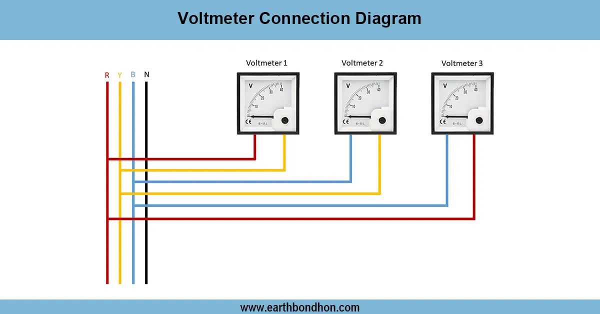
Voltmeter connection circuit diagram
Voltmeters are connected in parallel with whatever device's voltage is to be measured. A parallel connection is used because objects in parallel experience the same potential difference.
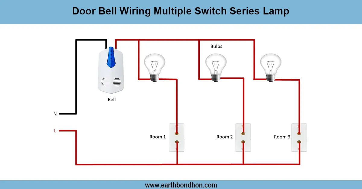
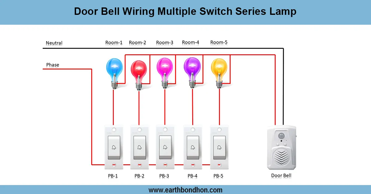
Door Bell Wiring Multiple Switch Series Lamp
Learn how to wire a doorbell with multiple switches and series lamps for efficient control and easy installation. Step-by-step wiring guide with diagrams included.
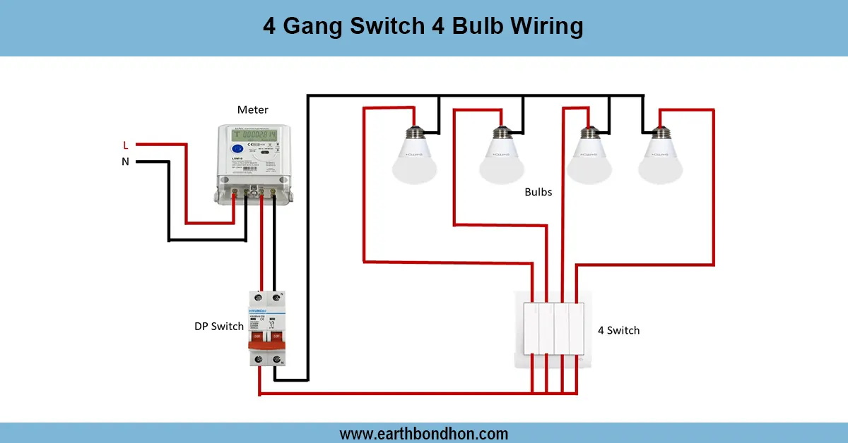
4 Gang Switch 4 Bulb Wiring
Learn how to wire a 4-gang switch to control 4 individual bulbs. Ideal for multi-light room setups with simple step-by-step wiring guide and diagram.
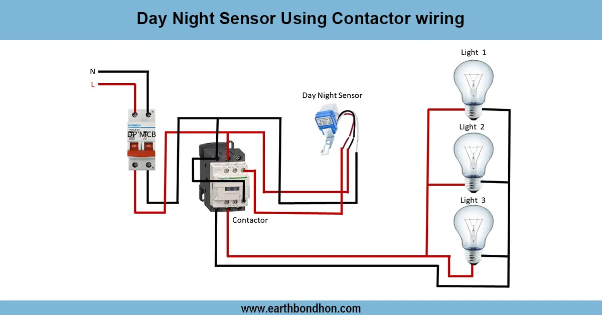
Day Night Sensor Using Contactor wiring
Automatic lighting control using a day-night sensor with a contactor for high-load circuits, ensuring safe, efficient, and hands-free operation.
Door Bell wiring Diagram
Learn the basic doorbell wiring diagram, connections, and components for a reliable home doorbell system installation with easy step-by-step guidance.
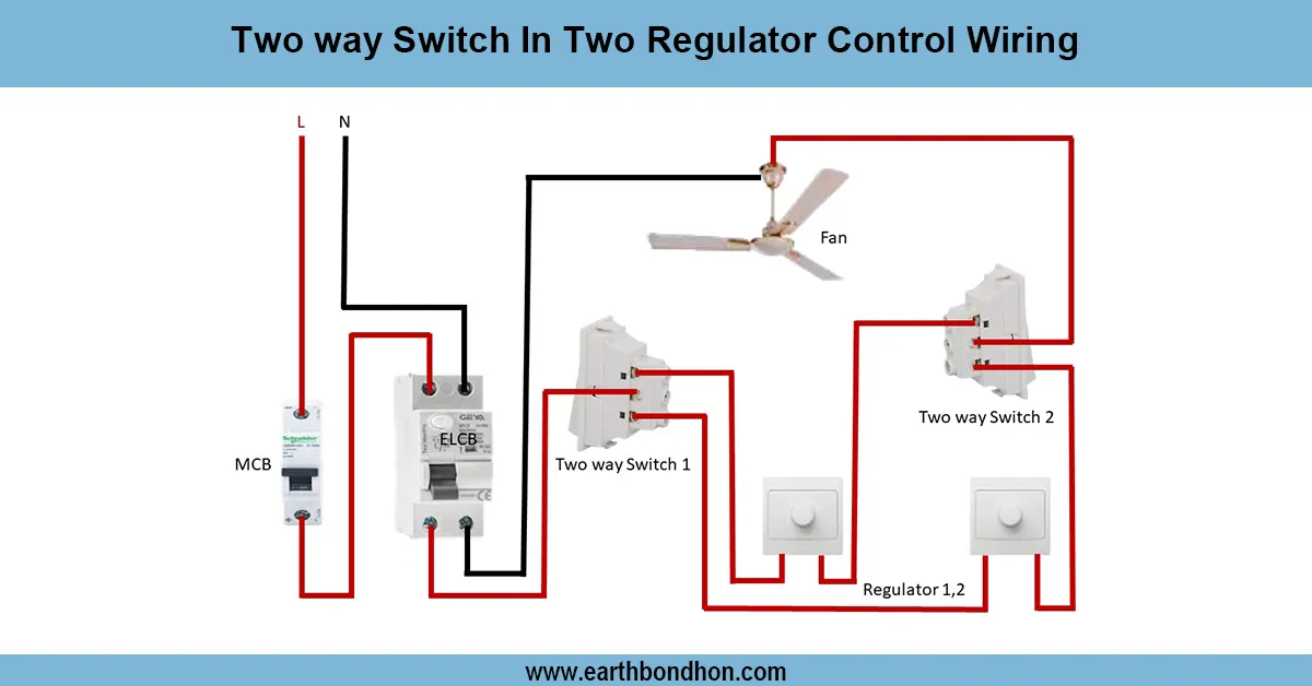
Two way switch fan regulator connection
Wiring diagram for controlling two separate light regulators from two locations using two-way switches for flexible ON/OFF control.