


Regulator Connection With Ceiling Fan
Learn how to wire a ceiling fan with a regulator to control fan speed efficiently. Ideal for homes, this guide explains the correct connection for safety and functionality.

fan regulator installation
The speed of a fan is controlled through a ceiling fan regulator, which varies the amount of voltage or current supplied to a fan motor. Proper connection will provide safe control of the fan and a safe and long life for the motor. This instruction illustrates how to connect a ceiling fan to a regulator and switch the usual way of wiring it within a domestic electrical system.
Ceiling Fan with Regulator Wiring Steps:
- Phase (Live) wire goes to the switch input terminal.
- Switch output connects to the regulator input terminal.
- Regulator output connects to the fan's Line terminal.
- Neutral (N) wire connects directly from board to the fan.
- Earth wire (if available) connects to the fan body for safety.
ceiling fan regulator wiring
A ceiling fan regulator is a very necessary piece that is incorporated to regulate the speed of the fan with the capacity to alter the voltage to the fan motor. Set in a common household arrangement, the regulator can be attached between the switch and the fan, and as such, you can switch the fan on/off and regulate its pace. The proper wiring sequence is as follows: Phase (live) wire to the switch, then the switch to the regulator, and the regulator to the fan line terminal. The fan is connected to the neutral wire, and when possible there should be an earth wire connected to the fan body to ensure safety. As a proper connection is made, the operation will be efficient, the life of the motor will be increased, and the safety will be improved. This guide gives a definite wiring diagram, component list, and installation procedures for connecting a ceiling fan with a speed regulator. Whether you want to replace an old one or install a new one, this tutorial is going to guide you on how to learn the right way of wiring and things to avoid. It is best suited to electricians, technicians, or someone that is just interested in learning about basic knowledge on how to install a fan.
ceiling fan wiring with switch and regulator
| Component | Description | Usage |
|---|---|---|
| Fan Regulator | Controls fan speed | Connected between switch and fan |
| Ceiling Fan | Electrical fan | Connected to regulator and neutral |
| SPST Switch | On/Off control | Connected to phase line |
Frequently Asked Questions - Regulator Connection With Ceiling Fan:
What is a ceiling fan regulator?
A device that controls the fan speed by regulating voltage or current.
How to wire a fan with a regulator?
Live → Switch → Regulator → Fan Line. Neutral goes directly to fan.
Does the regulator go before or after the switch?
It usually comes after the switch in home wiring.
Can I use a dimmer as a fan regulator?
No, dimmers are not suitable for fans and may damage the motor.
What type of switch is used with a fan?
A standard SPST switch is typically used for ON/OFF control.
How many wires are needed for a fan connection?
Minimum two wires: Line and Neutral; Earth is optional for safety.
Is earthing necessary for ceiling fans?
It is recommended for safety but not mandatory.
Can I connect two fans to one regulator?
Not recommended. Use separate regulators for each fan.
Do all regulators support all fan types?
Use only compatible regulators as per fan motor type (AC/BLDC).
What happens if regulator is bypassed?
Fan runs at full speed; you lose speed control.
Related Posts
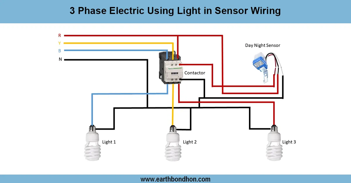
Manual Light sensor connection for street light
Wiring diagram for 3-phase electric systems using light sensors to automate lighting control, improving energy efficiency and safety in industrial and commercial setups.
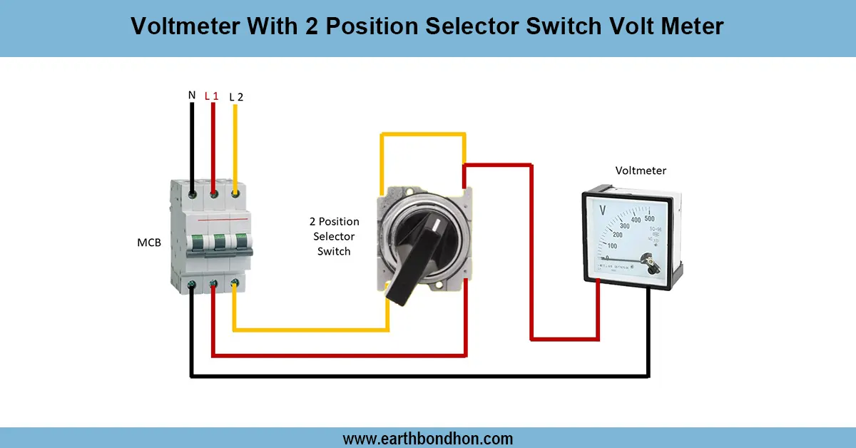
Selector Switch in Voltmeter Wiring
Learn how to wire a voltmeter with a 2-position selector switch to measure voltage from two sources or points safely and accurately.

Series Testing Board Connection
Learn how to wire a series testing board with multiple sockets and bulbs. Ideal for electricians and students testing AC appliances or basic electric setups.
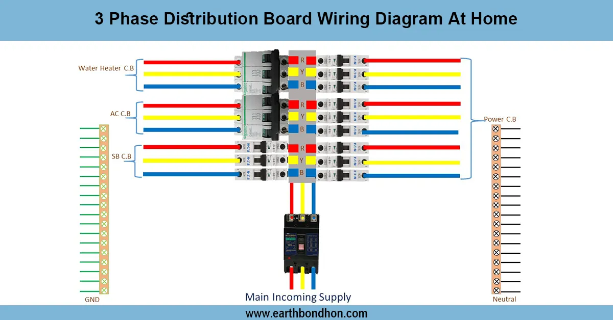
3-Phase Distribution Board wiring diagram
Simple 3-phase distribution board wiring diagram for home use, showing safe connection of power supply, breakers, neutral, and earth for residential electrical systems.
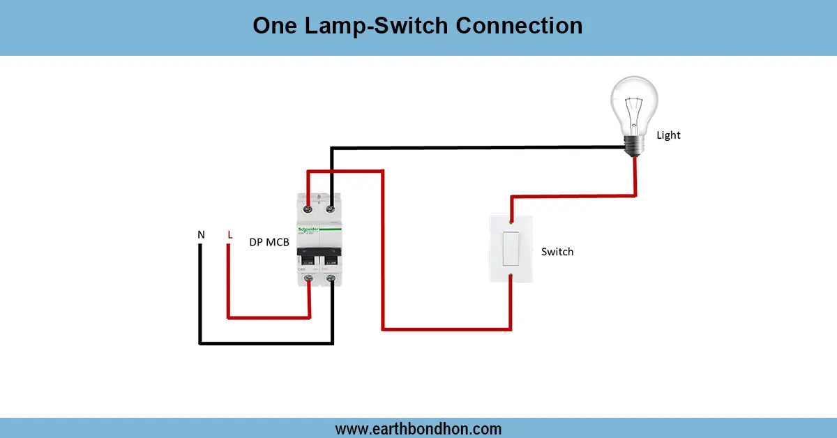
1 Way light Switch wiring Diagram
Learn how to wire a 1-way light switch to control a single light. Ideal for rooms, corridors, and small areas where one switch operates one light.
Power Socket Wiring Diagram
Learn how to wire a power socket with safety in mind. This guide includes diagrams, step-by-step instructions, and common wiring FAQs for home and industrial use.