


Single Phase House Wiring Diagram
Understand single-phase house wiring diagrams with clear steps for safe, efficient, and reliable home electrical connections.

electrical wiring single phase
A single-phase house wiring diagram constitutes an important map for safe electrical wiring in the home. It demonstrates the connection of power distribution at the main supply to different destinations like lights, fans, switches, and sockets with an even distribution of load. The ability to visibly distinguish parts such as breakers, switches, and wiring routes prevents errors and leads to adherence to the safety standards made by professionals as well as non-professionals. A good starting point to a safe, dependable electrical system is the use of a correct wiring diagram.
Formula & Table Summary:
Formula for calculating electrical load in single-phase wiring:
P = V × I
Where P is power in watts, V is voltage (usually 230V), and I is current in amperes. This helps determine the correct wire size and breaker rating.
home electrical wiring single phase
A single-phase house wiring diagram depicts the electrical connections, showing how the electrical wiring is made in a residence powered by a single-phase power supply. It is a bit simple, safe, and costly wiring suitable in residential houses where the electrical load is medium and provides an atmosphere of simplicity. Main distribution board, MCBs, switches, sockets, lighting points, and proper grounding are usually covered in the diagram. This knowledge of the diagram assists in safe installation, optimal energy use, and meets the electrical requirements. These diagrams are used by homeowners and electricians to program routing, find errors, and be able to maintain systems to prevent the occurrence of electrical hazards.
single phase wiring diagram
| Appliance | Power (W) | Current (A) |
|---|---|---|
| LED Bulb | 10 | 0.043 |
| Ceiling Fan | 75 | 0.326 |
| Refrigerator | 200 | 0.87 |
Frequently Asked Questions - Single Phase House Wiring Diagram:
What is a single-phase house wiring diagram?
It’s a schematic showing electrical connections for a single-phase supply in homes.
Why use single-phase wiring?
It’s cost-effective, simple, and ideal for residential loads.
What voltage is used in single-phase wiring?
Typically 220–240V in most countries.
How is power distributed in single-phase wiring?
Through a main distribution board feeding lighting and power circuits.
What safety devices are used in single-phase wiring?
MCB, ELCB, and proper grounding.
Can single-phase wiring handle high loads?
It’s suitable for moderate loads; heavy loads need a three-phase supply.
What wire size is used for single-phase house wiring?
Generally 1.5mm² for lighting, 2.5mm² for sockets.
How to troubleshoot single-phase wiring?
Check breakers, connections, and test voltage supply.
What is the difference between single and three-phase?
Single phase uses one alternating current, three phase uses three.
Can I install single-phase wiring myself?
Only if trained; otherwise, hire a licensed electrician.
Related Posts
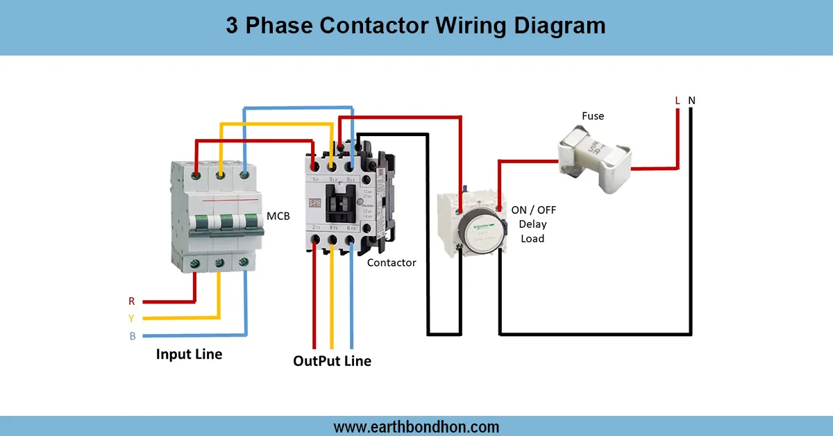
3-Phase contactor wiring diagram
Detailed 3-phase contactor wiring diagram showing power and control circuit connections for reliable switching of 3 phase motors and loads.
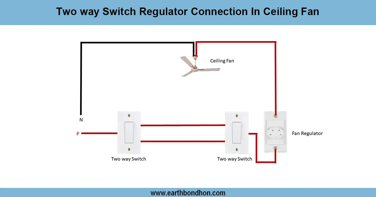
Ceiling Fan Regulator connection
Wiring diagram showing how to connect a two way switch with a regulator to control ceiling fan speed and ON/OFF from two locations.

Regulator Connection With Ceiling Fan
Learn how to wire a ceiling fan with a regulator to control fan speed efficiently. Ideal for homes, this guide explains the correct connection for safety and functionality.
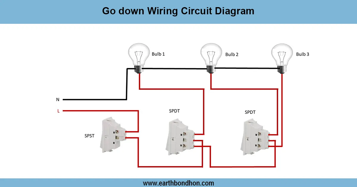
Go down Wiring Circuit Diagram
Learn the Go Down wiring circuit diagram with clear steps for safe, efficient electrical wiring. Perfect for warehouses and storage areas.
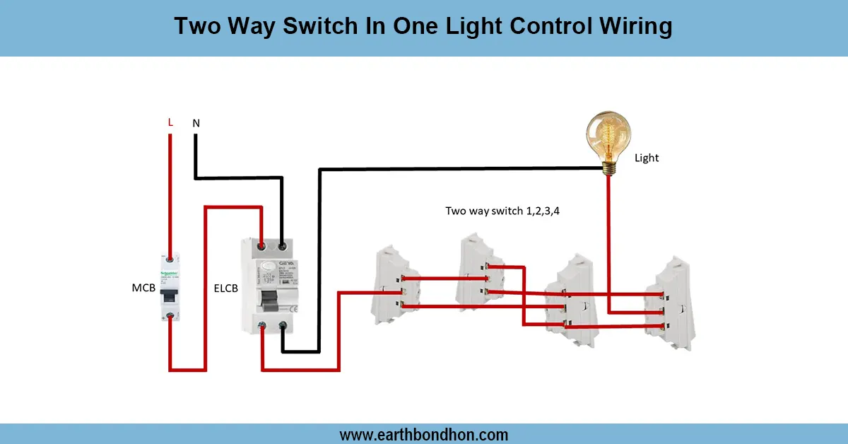
2-Way Light switch wiring circuit
Wiring diagram to control a single light from two locations using two-way switches for convenient ON/OFF switching in homes and offices.
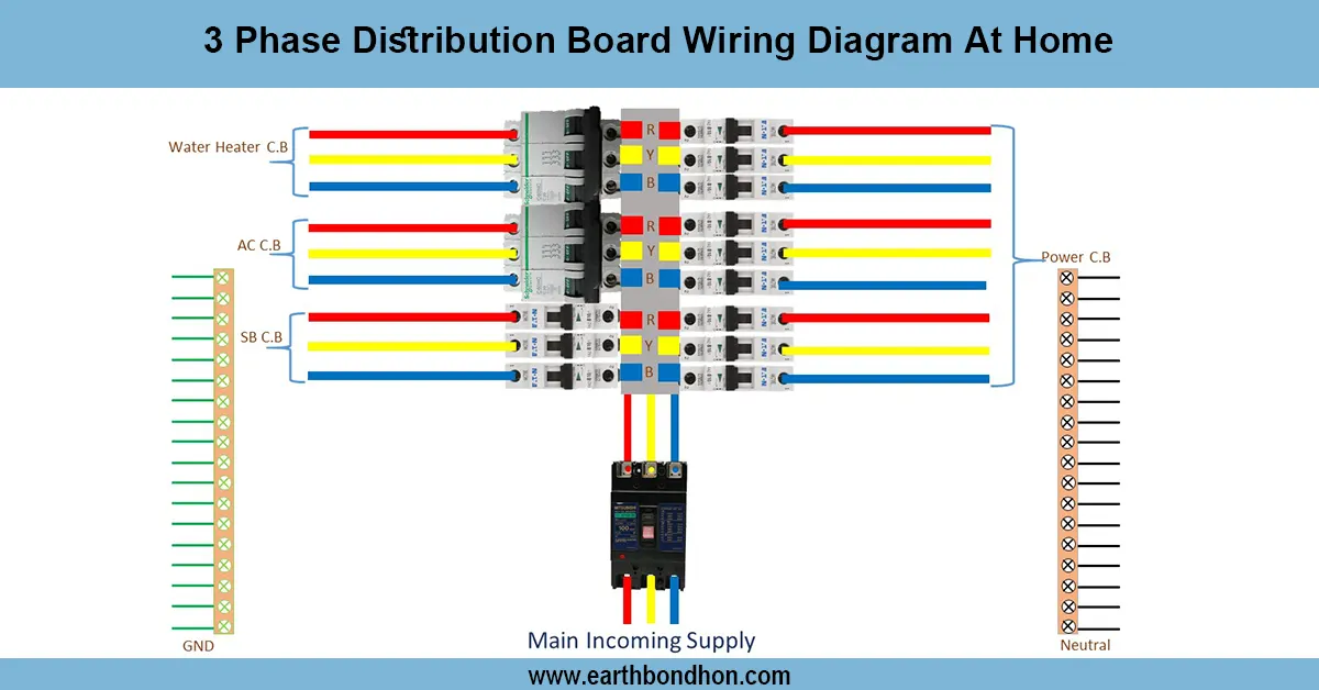
3-Phase Distribution Board wiring diagram
Simple 3-phase distribution board wiring diagram for home use, showing safe connection of power supply, breakers, neutral, and earth for residential electrical systems.