


12V Charging Indicator Circuit
Easily monitor your 12V battery charging status with this LED-based indicator circuit. A simple and efficient solution for battery health monitoring.

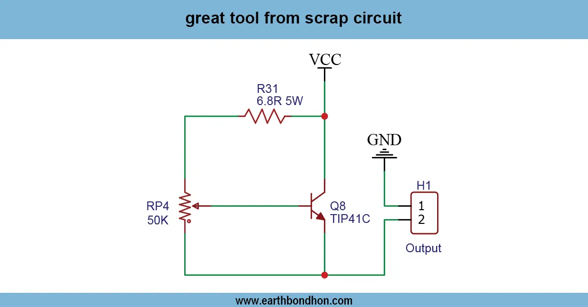
12v battery indicator using LED
The 12V charging indication circuit offers an easily understandable and accurate method of knowing the charging status of a 12V battery using simple components. With the inclusion of a comparator voltage or switching logic transistor, this circuit can allow users to effectively monitor battery health and curb battery overcharging. It is a vital instrument in the automotive, solar, and do-it-yourself electronics-related projects involving lead-acid or lithium batteries.
Formula & Table Summary:
The circuit typically works by comparing the voltage from the battery to a reference voltage. The LED turns ON or OFF depending on the result of this comparison.
- Vref = Reference voltage (e.g., from voltage divider)
- Vbat = Battery voltage
- LED ON when Vbat > Vref (fully charged)
- LED OFF when Vbat < Vref (still charging)
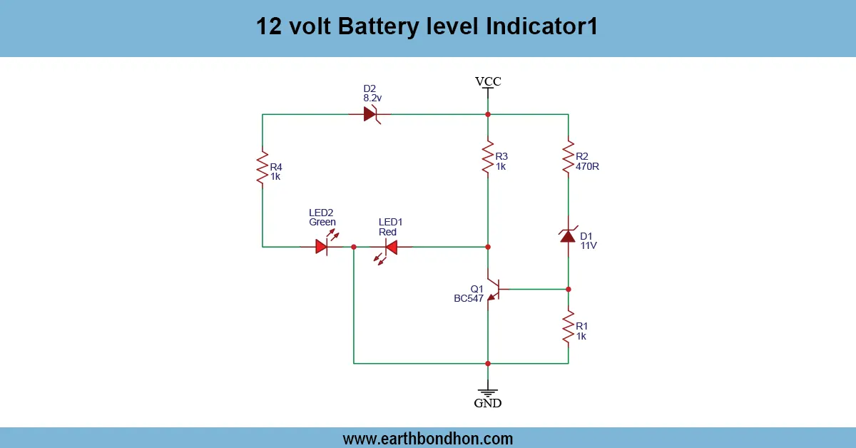
12v charging indicator
A 12V charging indicator circuit is a basic electronic project built with the objective of visually monitoring the charging status of a 12V battery. Its conventional detection of voltage levels is done via the use of LEDs and a voltage comparator such as LM393 or an op-amp. The LED indicator gradually changes color when the battery is fully charged (e.g., red to green). The project would fit perfectly in DIY battery management systems, solar systems, and automotive battery monitors.
battery charging indicator circuit
| Battery Voltage | LED Status | Battery State |
|---|---|---|
| 11.8V | Red ON | Charging |
| 12.0V | Yellow ON | Almost Full |
| 12.6V | Green ON | Fully Charged |
Frequently Asked Questions - 12V Charging Indicator Circuit:
What is a 12V charging indicator circuit?
It’s a simple electronic circuit that uses LEDs to show battery charging status in 12V systems.
How does this circuit work?
It monitors voltage levels and lights up LEDs based on whether the battery is charging or fully charged.
Can I use this for car batteries?
Yes, it's ideal for car or solar battery monitoring in 12V systems.
Which components are used?
Commonly used components are resistors, LEDs, and comparators like LM393 or transistors.
How many LEDs are used?
Typically 2 or 3 LEDs are used: Red for low, Yellow for charging, Green for full charge.
Is it safe for lithium batteries?
Use caution; lithium batteries require precise charging. Add protection circuits if needed.
Does it consume power while idle?
Very minimal power is consumed when idle, typically under a few milliamps.
Can I modify the voltage threshold?
Yes, by adjusting resistor values in the voltage divider or comparator circuit.
Is it beginner-friendly?
Yes, it's a great starter project for learning basic electronics.
Where can I use this?
Used in UPS, solar, automotive, or any 12V battery-based system to show charging status.
Related Posts
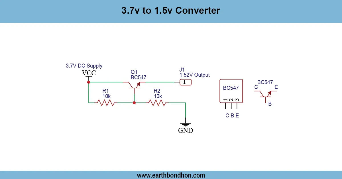
3.7V to 1.5V Converter
Learn how to convert 3.7V to 1.5V using a buck converter or voltage regulator. Ideal for low-voltage electronics like sensors, microcontrollers, or low-power LEDs.
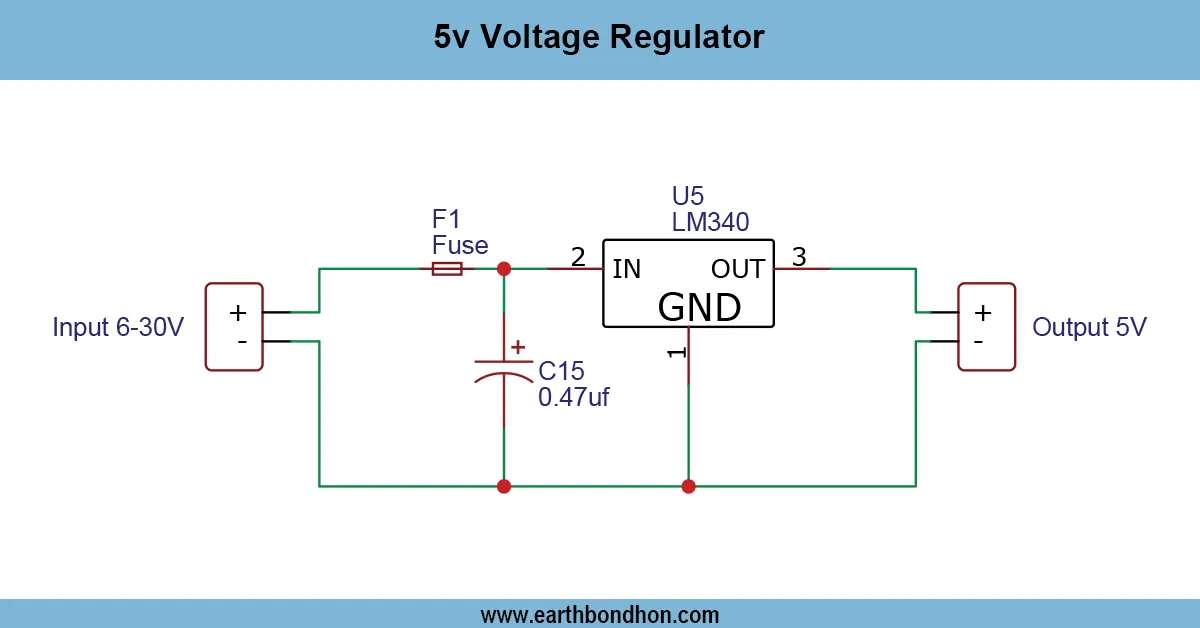
5V Voltage Regulator
Build a stable 5V DC power supply using the LM340 voltage regulator. Ideal for microcontroller circuits and small electronics projects.
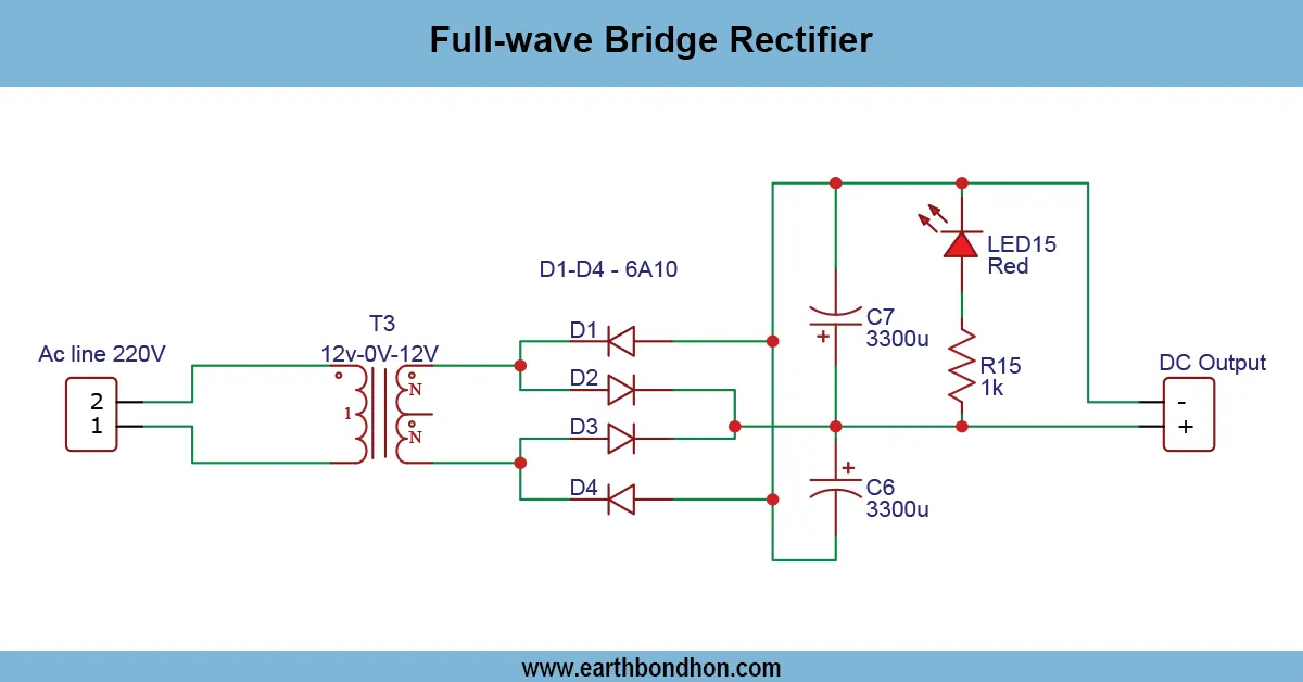
Full Wave Bridge Rectifier Project
Learn how a full-wave bridge rectifier works using 4 diodes and a transformer. Explore working principles, circuit diagrams, and practical applications.
Adjustable Voltage Regulator Project
Learn how to make an adjustable voltage regulator using LM317 or LM338. Perfect for DIY electronics projects requiring a variable DC output voltage.
12V Charging Indicator circuit
Design a simple 12V charging indicator circuit using LEDs and transistors to visually show battery charging and full status for automotive or solar battery systems.
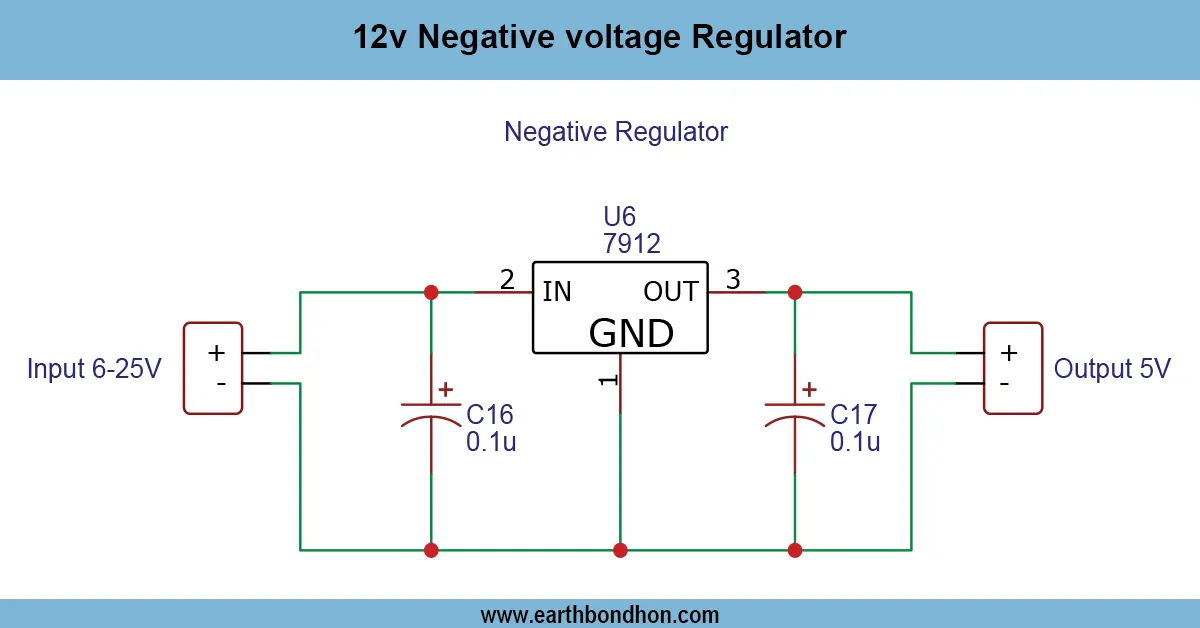
12V Negative Voltage Regulator
Learn how a 12V negative voltage regulator works. Circuit, applications, pinout, and FAQ included. Ideal for power supply stabilization in electronics projects.