

Full Wave Bridge Rectifier Project
Learn how a full-wave bridge rectifier works using 4 diodes and a transformer. Explore working principles, circuit diagrams, and practical applications.

4 diode full-wave rectifier
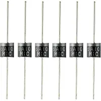
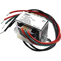
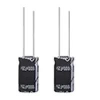
A circuit that converts AC (alternating current) to DC (direct current) by using 4 diodes organized in a bridge arrangement is also known as a full-wave bridge rectifier. This project contains the description of the circuit diagram, operating principle, and advantages of using a full-wave rectifier compared to a half-wave rectifier. The project is an essential yet practical project in power supply design, and is also an excellent project to perform as a student or when electronics are new to the student. It shows the alternating conductance of the diodes between each phase of AC, so that a smoother DC is generated. These comprise 4 diodes (1N4007), a center-tapped or a standard transformer, a filter capacitor, and a load resistor. This tutorial will have formulas, step-by-step explanations, and sample values of voltage to understand in better understand.
>Key Formulas for Full-Wave Bridge Rectifier:
- Vdc = (2 × Vm)/π ≈ 0.637 × Vm
- Vrms = Vm/√2
- Ripple Factor = (1.21 for full-wave)
- Efficiency = 81.2%
full-wave rectifier explanation
A full-wave bridge rectifier is a circuit that changes AC (alternating current) to DC (direct current) with four diodes connected in a most important position called the bridge position. This project describes the circuit, working principle, and benefits of a full-wave rectifier as compared to a half-wave rectifier. This project is of great importance in the design of power supply, a very important concept to students as well as beginners in electronics. It indicates how the diodes conduct alternating runs of the AC and make a smoother output of DC. It consists of 4 diodes (1N4007), a center-tapped or regular transformer and a filter capacitor, and a load resistor. Formulae, working explanations, and sample values of voltages are provided in this tutorial to understand.
bridge rectifier circuit
| AC Input (Vrms) | Transformer Vm | DC Output (Vdc) | Load Current (I) |
|---|---|---|---|
| 230V | 12V | 7.64V | 150mA |
| 110V | 6V | 3.82V | 75mA |
Frequently Asked Questions - Full Wave Bridge Rectifier Project:
What is a full-wave bridge rectifier?
A circuit using four diodes to convert AC into DC using both halves of the input signal.
Why use a bridge rectifier over half-wave?
It offers better efficiency, smoother output, and uses the entire AC cycle.
What components are required?
Four diodes (1N4007), transformer, capacitor, and load resistor.
What is the output of a bridge rectifier?
A pulsating DC voltage smoother than half-wave output.
Where is it used?
Power supplies, battery chargers, and DC motors.
How does the capacitor help?
It filters the DC output by reducing voltage ripples.
What is the efficiency of a full-wave rectifier?
About 81.2% under ideal conditions.
What is Peak Inverse Voltage (PIV)?
The maximum voltage a diode must withstand in reverse bias.
Can I use a center-tap transformer?
No, full-wave bridge doesn’t require center tap; it uses 4 diodes instead.
Is it suitable for low voltage applications?
Yes, commonly used for 5V, 9V, 12V DC power supplies.
Related Posts
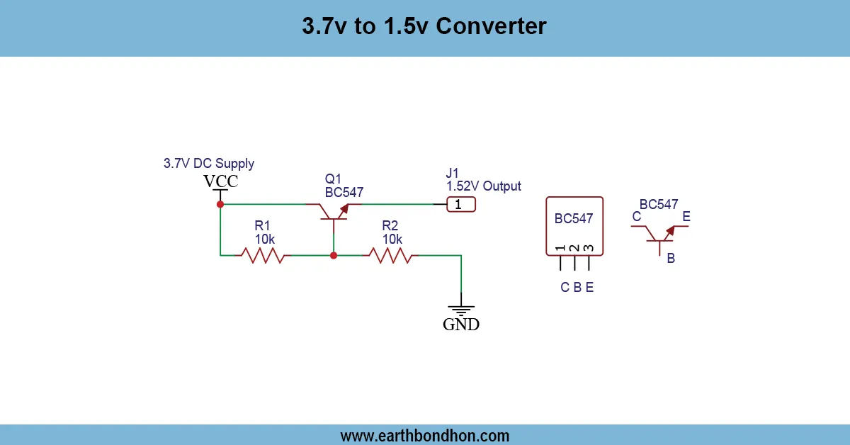
3.7V to 1.5V Converter
Learn how to convert 3.7V to 1.5V using a buck converter or voltage regulator. Ideal for low-voltage electronics like sensors, microcontrollers, or low-power LEDs.
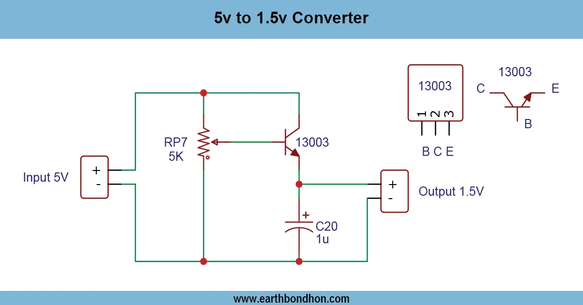
5V to 1.5V Converter Circuit
Learn how to convert 5V DC to 1.5V using a simple step-down (buck) converter. Perfect for low-power electronics like sensors, LEDs, and microcontroller peripherals.

12V Charging Indicator Circuit
Easily monitor your 12V battery charging status with this LED-based indicator circuit. A simple and efficient solution for battery health monitoring.
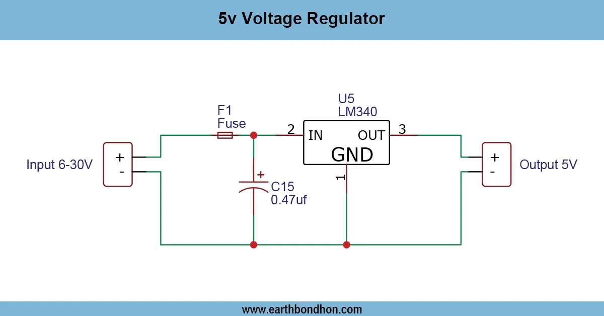
5V Voltage Regulator
Build a stable 5V DC power supply using the LM340 voltage regulator. Ideal for microcontroller circuits and small electronics projects.
Adjustable Voltage Regulator Project
Learn how to make an adjustable voltage regulator using LM317 or LM338. Perfect for DIY electronics projects requiring a variable DC output voltage.
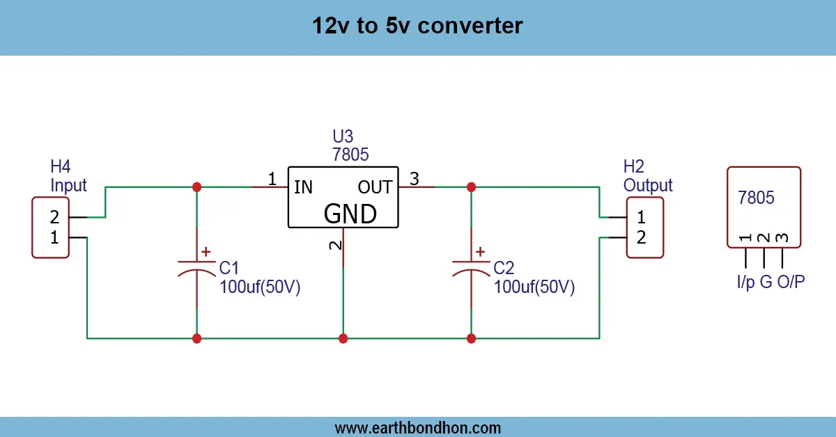
12V to 5V Converter
Learn how a 5V voltage regulator circuit works, circuit diagram, applications, and how to regulate 12V or higher voltage down to stable 5V DC for electronics.