


Ceiling Fan Regulator connection Wiring
Learn how to wire a ceiling fan with a regulator. Includes simple step-by-step diagram for proper connection of live, neutral, and regulator terminals.

fan regulator installation
Regular wiring of a ceiling fan involves a simple electrical procedure that assists in managing the rate of the fan very well. The arrangement involves having the live connection to the switch, to the switch, to the regulator, and finally to the fan. There is a neutral wire straight into the fan. It is such a method that can be easily used at home, in offices, and in other commercial areas where fan speed control is required. Go through this guide to get a clear idea of understanding the connection in terms of diagram, components, and working.
Ceiling Fan with Regulator Wiring Steps:
Wiring Formula:
- Phase (L) → Switch → Regulator → Fan (L)
- Neutral (N) → Fan (N)
- Earth (E) → Fan Body (if available)
Component Table:
- Switch – On/Off control
- Regulator – Fan speed control
- Ceiling Fan – Output load
- Wire (Red/Black/Green) – Phase, Neutral, Earth
ceiling fan regulator wiring
Ceiling fan regulator connection. A fan is wired to a switch and a regulator that is used to vary the voltage and hence the speed. Most circuits are built so that there is a live (phase) wire with a switch connected to it. There is a wire connected to the switch and then connected to the regulator. The outlet of the regulator then becomes connected to the phase outlet of the fan. The neutral wire goes straight between the power source and the fan neutral wire. Where possible, there should be a connection to an earth (ground) wire to provide safety. This way of control provides the fan speed operation in the most effective way, preventing overloads or inappropriate functioning. Fan regulators tend to be resistive or electronic (capacitive) in form, and the newer electronic forms tend to be more energy efficient. It is an appropriate connection to ceiling fans, wall-mounted fans, or pedestal fans. When you learn the essentials of this basic wiring diagram, it will keep you safe and make certain that the installation goes smoothly, whether you are changing an old unit or installing new wiring at either home or commercial premises. Power should always be shut down at its main before fitting any wires, and ensure that good connections of wire are always used.
ceiling fan regulator wiring
| Component | Connection From | Connection To |
|---|---|---|
| Switch | Phase (L) | Regulator Input |
| Regulator | Switch Output | Fan Phase Terminal |
| Neutral Wire | Power Source | Fan Neutral Terminal |
| Earth Wire | Ground | Fan Body |
Frequently Asked Questions - Ceiling Fan Regulator connection Wiring:
How does a ceiling fan regulator work?
It controls the voltage going to the fan motor to adjust speed.
Where should a regulator be connected?
Between the switch and the fan's phase terminal.
Can I install a fan without a regulator?
Yes, but the fan will run at full speed only.
Which wire goes to the regulator?
The live wire from the switch connects to the regulator input.
Is a fan regulator AC or DC?
It operates on AC, same as the fan.
What color is the live wire for fan connection?
Usually red or brown in standard wiring.
Can I use any regulator for any fan?
Use compatible regulator types (resistive or electronic).
How many wires go to a ceiling fan?
Usually 2 or 3 — Phase, Neutral, and optional Earth.
Can I use dimmer as a fan regulator?
Not recommended as fan motors need specific control circuits.
Is it safe to do this wiring myself?
Yes, with precautions. Turn off the main supply first.
Related Posts

Single Phase House Wiring Diagram
Understand single-phase house wiring diagrams with clear steps for safe, efficient, and reliable home electrical connections.
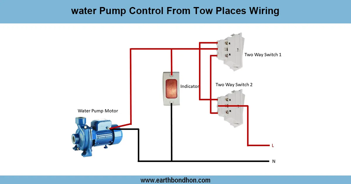
Water pump control from two places
Step-by-step wiring diagram for controlling a water pump from two different locations using two-way switches, ensuring convenience and safety.

4 Switches 1 Light Control
Learn how to wire 4 switches to control 1 light from multiple locations using intermediate and two-way switches for staircases, hallways, or large rooms.

Commutable light Wiring Diagram
Conmutable wiring allows controlling a single light from two switches, ideal for staircases or hallways, using two-way (SPDT) switches for convenience and safety.
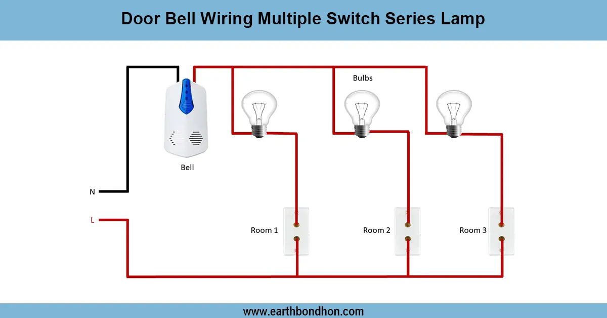
Door Bell Wiring Multiple Switch Series Lamp
Learn how to wire a doorbell with multiple switches and series lamps for efficient control and easy installation. Step-by-step wiring guide with diagrams included.
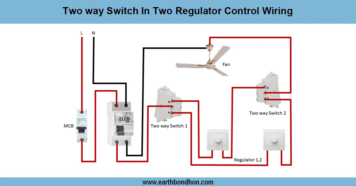
Two way switch fan regulator connection
Wiring diagram for controlling two separate light regulators from two locations using two-way switches for flexible ON/OFF control.